
K-LOK 150A Mini-Cam Single-Pole Cam-Type Connectors
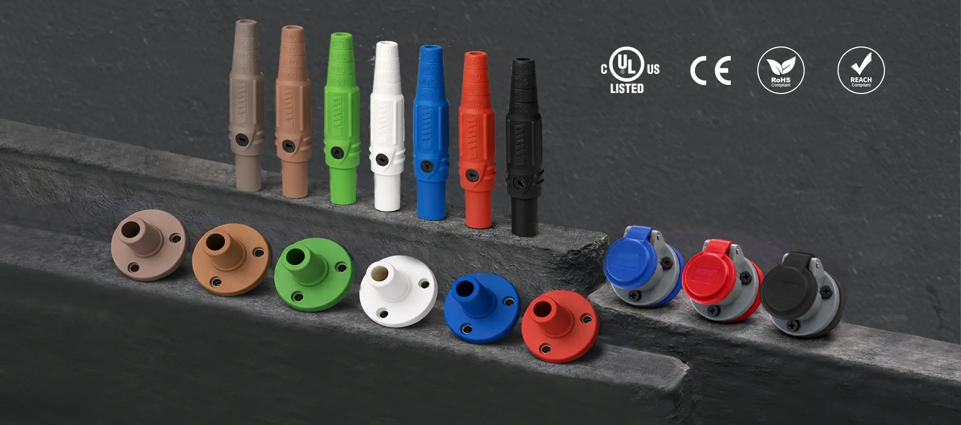
K-LOK 150A Mini-Cam connectors support compact temporary power runs with a 150A, 600V rating, #8 to #2 AWG cable range, brass contacts, and double set-screw termination. A 105°C Santoprene TPV body, longer POM insulation sleeve, raised alignment arrow, and engraved cable cut-off mark help crews make clean, repeatable field terminations. Compatible with other brands of 150A cam-type connectors.*
Note: De-energize the circuit before mating or unmating; K-LOK connectors are not intended for load-break disconnection.
Find Your Configuration
Add your color suffix to the base SKU to get the full part number. Example: KL-150LF + Black (BK) = KL-150LFBK. See the color table below.
Phase Identification Colors
K-LOK 150A is available in 7 phase-identification colors across every configuration. Select the color that matches your phase convention or fleet standard.
Need a color not listed? Contact KUPO to discuss custom or additional phase colors for fleet standardization. For Orange and Yellow, see the K-LOK 400A family.
Built for the Field

| Feature | Why It Matters in the Field |
|---|---|
| Inner POM insulation sleeve | An inner POM (polyoxymethylene) insulation sleeve adds heat resistance and strength, and a non-metallic retaining screw locks the brass contact firmly in position. |
| Double set-screw termination with extra long set screws | Two set screws secure the conductor from both sides for a balanced grip. Extra-long set screws are included for smaller cable sizes (#8 AWG), eliminating the "almost fits" problem and reducing field rework when cable gauges vary across a project. |
| Raised arrow alignment indicator | A visible, molded arrow on the connector body shows correct mating orientation at a glance. Helps crews mate connectors correctly in high-pressure, low-light environments where mistakes cost time and create safety risk. |
| Tension hole anti-loosening design | A dedicated tension hole feature helps reduce loose mating over repeated connection and disconnection cycles. This matters on rental fleets and high-turnover event sites where connectors see hundreds of mate/unmate cycles per season. |
| UV-resistant Santoprene body with engraved cut-off ID | The TPV body compound is rated to 105 degrees Celsius and resists UV degradation, oil, and common industrial chemicals. The engraved cable cut-off reference line gives every technician a consistent cable preparation reference, reducing variability across crews. |
| Non-conductive POM retaining pin | Locks the contact firmly in position without creating accidental current paths. POM is non-conductive and corrosion-resistant, eliminating metallic failure modes in wet or humid environments. |
Technical Specifications
| Specification | Value |
|---|---|
| Maximum Current Rating | 150A |
| Maximum Voltage Rating | 600V |
| Cable Range | #8 to #2 AWG (outside diameter up to 13.60 mm) |
| Termination | Double set-screw. Extra long set screws included for smaller cables. |
| Contact Material | Brass |
| Body Material | Santoprene (TPV), rated 105°C, UV-resistant |
| Insulation Sleeve | POM (polyoxymethylene) |
| Retaining Pin | POM, non-conductive |
| Certification | cULus Listed to UL 1691 and CSA C22.2 No. 1691-12 (UL File E332947) |
| Compliance | RoHS compliant |
Certifications and Compliance
| Certification / Standard | Detail |
|---|---|
| cULus Listed | Listed by UL for the United States and Canada under UL File E332947. |
| UL 1691 / CSA C22.2 No. 1691 | Standard for Single Pole Locking-Type Separable Connectors. The applicable product safety standard for this connector family in North America. |
| Environment Rating | UL Type 3R when mated (UL 1691 requires this for cam-type devices). Suitable for indoor or outdoor use with protection against falling dirt, rain, sleet, snow, and external ice formation. |
| RoHS | Compliant with RoHS (Restriction of Hazardous Substances) Directive. No restricted materials in the contact, body, or retaining hardware. |
For project submittal packages, compliance documentation, or application-specific engineering questions: contact KUPO Engineering.
Downloads
Download the documents you need to complete a submittal package, mechanical design check, or procurement specification.
| Document | Format | Download |
|---|---|---|
| Product Family Datasheet | Download | |
| Full Catalog Extract | Download | |
| Installation and Termination Guide | Download | |
| 2D Drawings (DXF / DWG) | ZIP | Download |
| 3D CAD Models (STEP / IGES) | Download | |
| Compliance Pack (UL, RoHS) | ZIP | Download |
Need a document not listed here? Contact us and we will prepare it for your submittal package.
Installation and Wiring Guidance
K-LOK 150A requires no special tools for field assembly and disassembly. Follow the steps below for the correct termination procedure. Inline and panel mount installations use different processes.
Inline Connector Installation
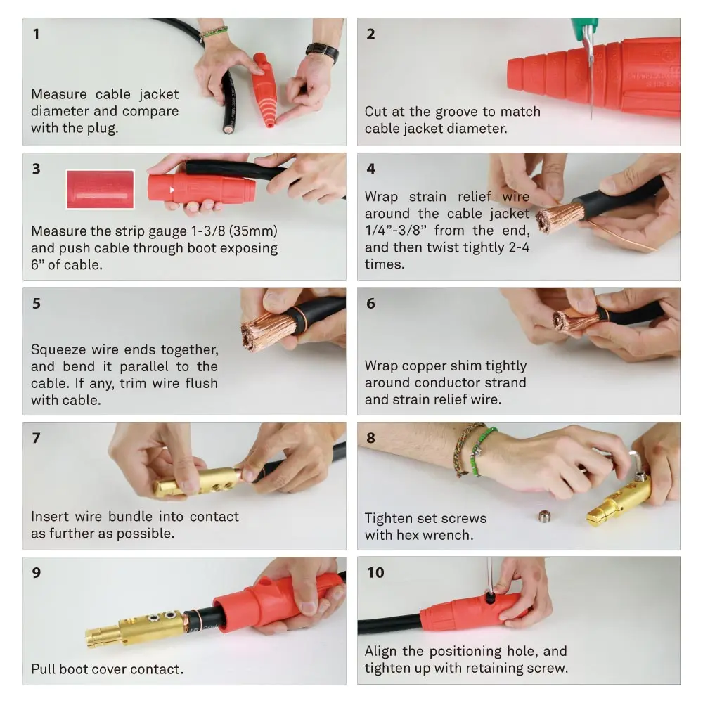
1. Measure the cable jacket diameter and compare with the connector body.
2. Cut the cable jacket at the groove that matches the jacket diameter.
3. Strip the conductor to the required gauge length and push the cable through the boot.
4. Wrap strain relief wire around the cable jacket near the end and twist tightly.
5. Squeeze wire ends together and bend parallel to the cable. Trim stray wire flush.
6. Wrap copper shim tightly around the conductor strand and strain relief wire.
7. Insert the wire bundle into the brass contact as far as possible.
8. Tighten the double set screws using a hex wrench. Use extra long set screws for #8 AWG cable.
9. Pull the boot cover over the contact.
10. Align the positioning hole and tighten the retaining pin.
Threaded Stud Panel Mount Receptacle Installation
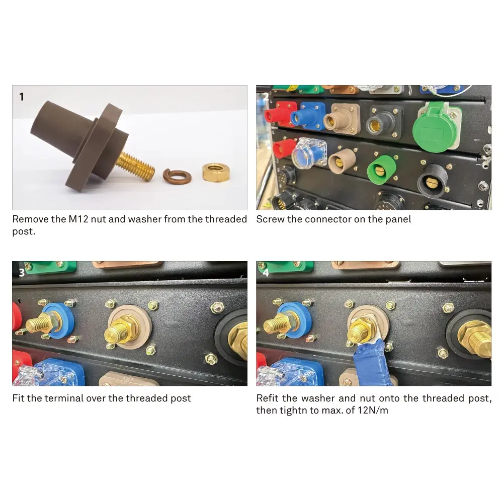
1. Remove the nut and washer from the threaded post on the connector body.
2. Screw the connector onto the panel through the panel cutout.
3. Fit the terminal over the threaded post from the rear of the panel.
4. Refit the washer and nut onto the threaded post. Tighten securely. Do not over-torque.
For detailed strip lengths, set-screw torque values, and inspection checklists, download the Installation and Termination Guide (PDF).
Frequently Asked Questions
Can I disconnect a K-LOK 150A connector while the circuit is live?
No. K-LOK single-pole connectors are not rated for load-break disconnection. Pulling a connector while current is flowing can create an electrical arc that damages the contact surfaces, degrades the insulating housing, and poses a serious risk of burns, electrical shock, or fire. Always de-energize the circuit at the breaker or distribution panel, verify it is dead using a voltage tester, and only then disconnect. This applies to both inline and panel mount configurations.
Will K-LOK 150A connectors mate with other brands of 150A cam-type connectors?
K-LOK 150A connectors are designed to be compatible with other brands of 150A cam-type connectors, so you can introduce K-LOK into an existing power distribution system without replacing everything at once. If you are running a mixed fleet or specifying K-LOK alongside another brand, contact KUPO for the cross-compatibility statement document, which lists confirmed mating configurations and any pairings to avoid. *Compatibility is based on dimensional interchangeability of the cam-type interface. Always verify mating suitability for your specific application.
Is K-LOK 150A UL listed?
K-LOK 150A connectors are cULus Listed under UL File E332947, to UL 1691 (Standard for Single Pole Locking-Type Separable Connectors) and CSA C22.2 No. 1691-12, so the listing covers the United States and Canada. They are rated UL Type 3R when mated for outdoor use. You can reference the certification in bid documents and spec packages. For a compliance pack with certificate copies, contact KUPO.
What cable types and sizes are supported?
K-LOK 150A accepts #8 to #2 AWG conductors with an outside diameter up to 13.60 mm. For smaller cables at the #8 AWG end of the range, extra-long set screws are included to ensure a secure grip on the smaller diameter. This eliminates the need for adapter sleeves or improvised workarounds when your cable gauge varies across a project. Copper conductors only.
What is the difference between 150A and 400A K-LOK connectors?
The 150A Mini-Cam family is physically smaller and designed for lighter-duty temporary power applications with #8 to #2 AWG cable. The 400A family handles #6 AWG to 4/0 AWG and is built for high-current feeder runs. Both families share the same design philosophy: brass contacts, Santoprene body, POM retaining hardware, double set-screw termination, and UL listing (cULus on the 150A, UL on the 400A). Choose 150A when your circuit load and cable size fall within the Mini-Cam range. Choose 400A when you need higher ampacity or larger cable accommodation.
Can I use K-LOK 150A connectors outdoors?
Yes. K-LOK 150A connectors are rated UL Type 3R when mated, meaning they are designed for indoor or outdoor use with protection against falling dirt, rain, sleet, snow, and external ice formation. The Santoprene body compound is UV-resistant and rated to 105 degrees Celsius. These connectors are widely used in outdoor entertainment power distribution, construction site temporary power, film and television location shoots, and generator-to-distribution connections.
What does the inner insulation sleeve do?
The K-LOK 150A has an inner POM (polyoxymethylene) insulation sleeve that adds heat resistance and strength, and a non-metallic POM retaining screw that locks the brass contact firmly in position.
Do I need special tools to assemble K-LOK 150A connectors?
No. K-LOK 150A connectors are designed for tool-simple assembly. Inline connectors require only a wire stripper and a standard screwdriver or hex wrench for the set screws. Panel mount receptacles require the same plus a wrench for the mounting nut. No hydraulic crimpers, proprietary dies, or brand-specific tooling are needed. This keeps your crews moving fast during load-in and makes field re-termination practical without specialized equipment.
Need help choosing K-LOK 150A?
KUPO can help confirm configurations, cable sizing, compatibility, fleet pricing, and documentation.
*Compatibility with other brands of 150A cam-type connectors is based on dimensional interchangeability of the cam-type interface. KUPO recommends verifying mating suitability for your specific application. Contact KUPO Engineering for the cross-compatibility statement.