
PowerFit 400A Single-Pole Power Connectors
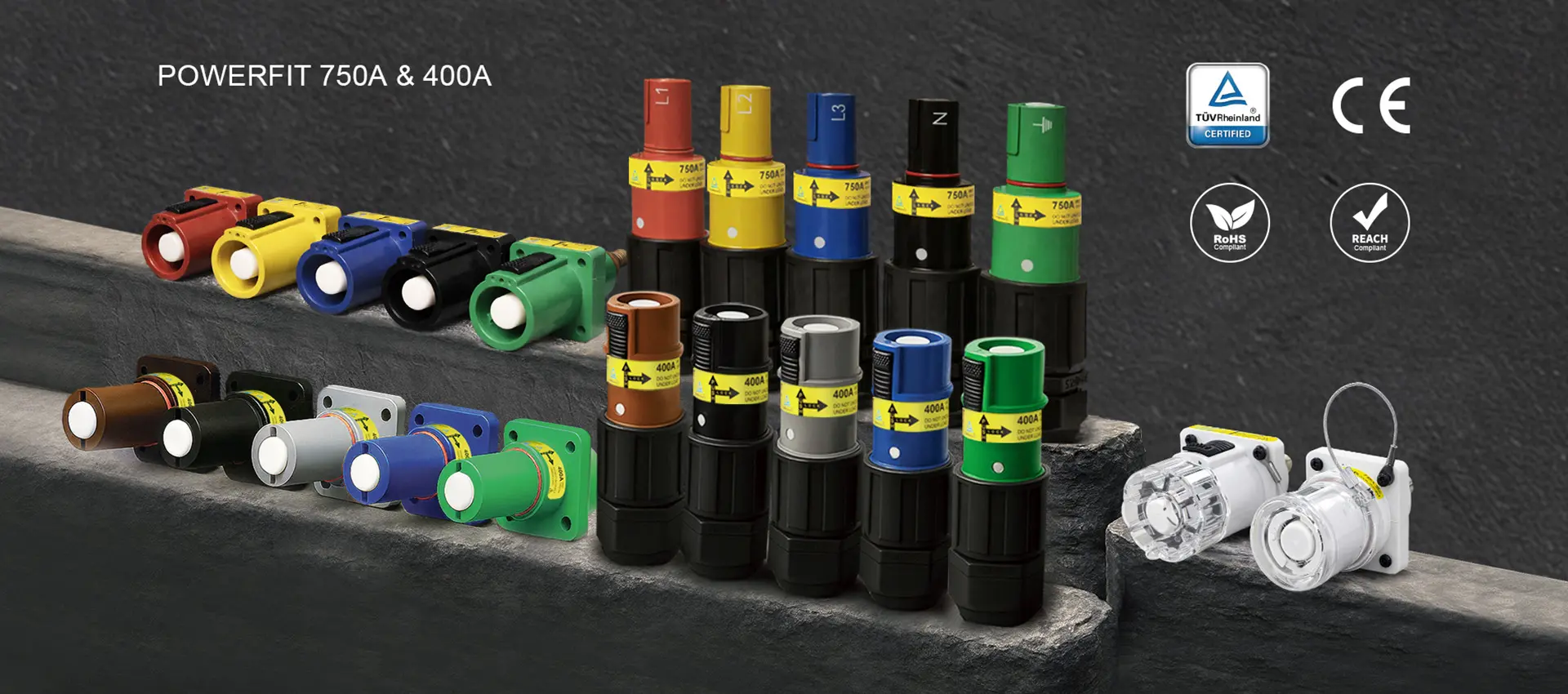
PowerFit 400A single-pole connectors bring IP67-sealed performance to high-current temporary and semi-permanent power distribution. Rated 400A, the system supports up to 1000V AC/DC with silver-plated brass contacts, 0.1 milliohm contact resistance, and a push-and-twist key-release mechanism. Phase-encoded SKUs, TÜV Rheinland certification to IEC 61984, CB and UKCA certificates, CE marking, and RoHS/REACH compliance support reliable specification across European and IEC-standard markets. Compatible with major brands of single-pole power connector.*
Note: De-energize the circuit before mating or unmating; PowerFit connectors are not intended for load-break disconnection.
Understanding Source and Drain
PowerFit uses Source and Drain to describe connector roles, not "male" and "female." Understanding this terminology is essential for correct system wiring.
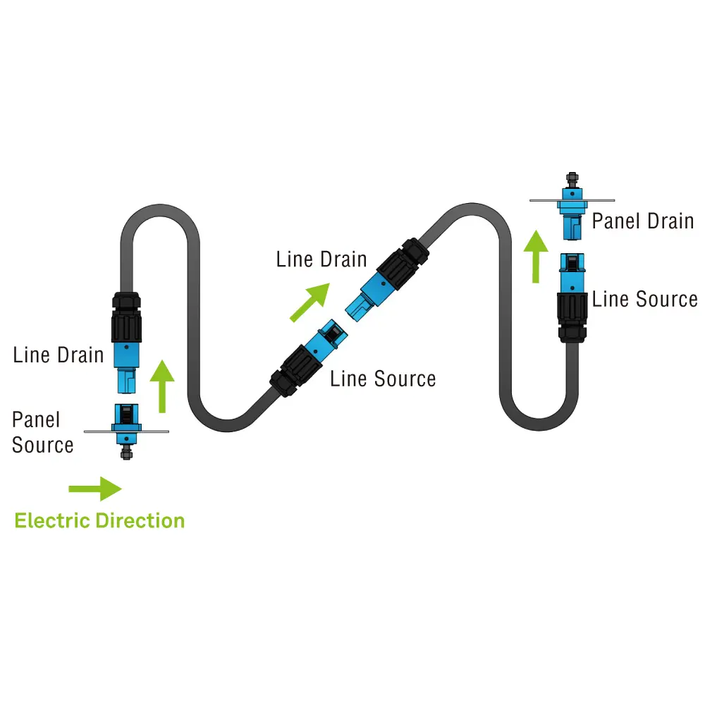
Electric direction: Panel Source → Line Drain ↔ Line Source → Panel Drain
| Term | Contact Type | Key Feature | Mating Rule |
|---|---|---|---|
| Source | Male contact (pin) | Key-release pin for intentional, tool-free disconnection | Panel Source mates with Line Drain. Line Source mates with Line Drain. |
| Drain | Female contact (socket) | Silicone O-ring for IP67 sealing when mated | Panel Drain mates with Line Source. Line Drain mates with Line Source. |
Simple rule: Source always connects to Drain. Key-release pin (Source only) allows controlled disconnection. De-energize before mating or unmating.
Find Your Configuration
PowerFit 400A connectors are available in four configurations. Line connectors mount on cable with an ergonomic rubber grip and M40 cable gland. Panel connectors mount through a 42 × 42mm cutout with an M12 threaded post. All configurations are available in all 8 housing colors across 13 phase-specific SKU codes.
Line connectors carry the suffix -S120M40A (set screw, 120mm² cable, M40 gland, A-range bushing). Panel connectors have no suffix after the color code.
Phase-Encoded Color System
PowerFit is available in 8 housing colors with phase-encoded SKUs to prevent cross-convention wiring errors. The same physical color can represent different phases in different regional standards. The SKU prefix (1BK vs 2BK vs NBK) makes the electrical assignment unambiguous.
Shop by phase
Why phase-encoded SKUs matter: Black appears as 1BK (Phase A in North America), 2BK (Phase B in Europe), and NBK (Neutral in Australia). Ordering by phase code instead of color alone prevents dangerous cross-convention wiring errors. *Verify specific brand compatibility with KUPO before mixing connector brands.
International Phase Color Convention
Select the connector color that matches the phase convention for your region and system voltage.
| Region | L1 | L2 | L3 | N | Ground |
|---|---|---|---|---|---|
| NA 120/208V 1 | Green / G-Y | ||||
| NA 277/480V 2 | Green / G-Y | ||||
| IEC 60445 3 | Green-Yellow | ||||
| AU/NZ Legacy 4 | Green-Yellow | ||||
| China 5 | Green-Yellow |
1 North America 120/208V (NEMA / NEC)
2 North America 277/480V (NEMA / NEC)
3 Europe, UK, Australia (current IEC 60445)
4 Australia / New Zealand legacy (pre-IEC)
5 China (GB 50303)
G-Y = Green-Yellow (earth/ground)
Built for Demanding Environments
| Feature | Why It Matters in the Field |
|---|---|
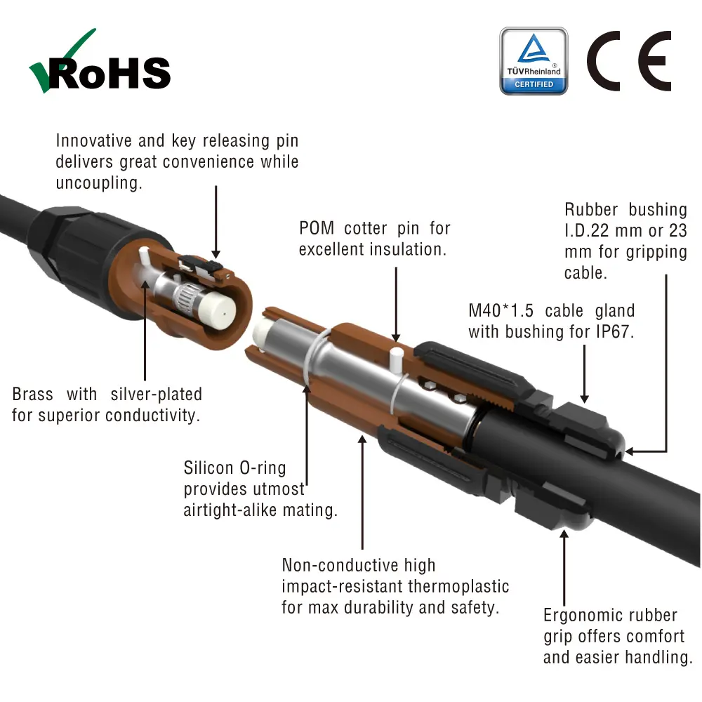
| IP67 sealed when mated | Complete protection against dust ingress and temporary water immersion (up to 1 meter, 30 minutes). Deploy in rain, mud and coastal environments without additional weatherproofing. IP67 covers temporary immersion, not high-pressure water jets. The silicone O-ring on Drain connectors creates the waterproof seal. |
| Silver-plated brass contacts | 0.1 milliohm contact resistance. Reduces resistive heating at sustained high-current loads, extending contact life and improving efficiency up to the full 400A rating. |
| Push-and-twist with key-release pin | Secure mechanical lock that requires intentional action to disconnect. The key-release pin on Source connectors can be operated tool-free, or with a small slotted screwdriver. No accidental disconnection under vibration or cable tension. |
| UL94-V0 flame rating | The top rating in the UL94 vertical burn (V) series. Housing self-extinguishes within 10 seconds with no flaming drips. |
| 400A maximum | Line connectors terminate 120mm² cable with double set screws; panel connectors use an M12 threaded post. |
| 1000V AC/DC maximum | A higher voltage rating than 600V-rated connectors. Supports higher-voltage distribution systems, battery storage, and renewable energy applications. |
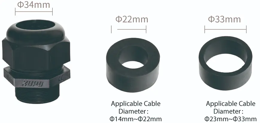
| Configurable cable gland system | Standard gland (CG-M4015-32) ships with two rubber bushings (Φ22mm and Φ33mm) covering cable Φ14mm to Φ33mm. Compact gland (CG-M4015) for mid-range cables. Optional M50 upgrade (CG-M5015-40) with adapter ring for larger cables. One connector body, multiple cable entry options. |
| Phase-encoded SKU system | 8 housing colors with phase-specific SKU codes prevent cross-convention wiring errors. The same color can carry different phase assignments in different regions, and the SKU prefix makes the assignment unambiguous. |
Technical Specifications
Electrical
| Current rating | 400A maximum |
| Voltage | 1000V AC/DC maximum |
| Test voltage | 4500V AC |
| Short-time withstand current | 16 kA for 1 s (short-time withstand) |
| Insulation resistance | >5000 megaohms at 500V AC |
| Contact resistance | 0.1 milliohms |
Mechanical
| Set screw torque (Line) | 10.5 N·m minimum |
| Nut torque (Panel) | 12 to 14 N·m maximum |
| Cable gland (standard) | CG-M4015-32, M40 × 1.5, two bushings (Φ22mm + Φ33mm) |
| Panel cutout | 42 × 42mm, 4 × Ø5.5mm fixing holes |
| Mating cycles | 500 |
Materials
| Housing | High impact-resistant thermoplastic, UL94-V0 |
| Contact | Brass, silver-plated |
| O-ring | Silicone (Drain connectors) |
| Cotter pin | POM (Polyoxymethylene) |
| Cable gland / bushing | Nylon and rubber (Line connectors) |
| Nut and washer | Brass (Panel connectors) |
Dimensions by Configuration
| Configuration | Total Length / Depth | Body Diameter | Key Dimension |
|---|---|---|---|
| Line Drain (PFLD) | 190mm | Ø32.5mm | M40 cable gland |
| Line Source (PFLS) | 170mm | Ø43.5mm | M40 cable gland |
| Panel Drain (PFPD) | 72.2mm depth | Ø37.0mm | 55.0mm flange, Ø32.5mm thread |
| Panel Source (PFPS) | 50.7mm depth | Ø42.5mm | 55.3mm flange, Ø43.5mm thread |
Panel cutout: 42 × 42mm for all panel configurations. Contact KUPO for detailed dimensional drawings (DXF/DWG).
Accessories and Companion Products
Cable Gland System
PowerFit line connectors use a configurable cable gland system that lets you match the seal to your exact cable diameter. The standard gland ships with every line connector. Compact and M50 options are available separately.
| Part Number | Product | Cable Range | Notes |
|---|---|---|---|
| CG-M4015-32 | Standard Cable Gland (M40) | Φ14 to 22mm + Φ23 to 33mm | Ships with two rubber bushings (Φ22mm and Φ33mm). Standard on all line connectors. |
| CG-M4015 | Compact Cable Gland (M40) | Φ18 to 28mm | Single Φ28mm bushing. Smaller outer diameter for tighter builds. |
| CG-M5015-40 | M50 Cable Gland (optional) | Φ32 to 40mm | For larger cables (240mm²+). Requires CG-M40-M50 adapter ring. |
| CG-M40-M50 | Adapter Ring | N/A | M40 external thread to M50 internal thread. Enables M50 gland on standard PowerFit connectors. |
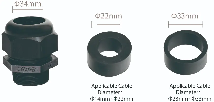 CG-M4015-32 |
 CG-M4015 |
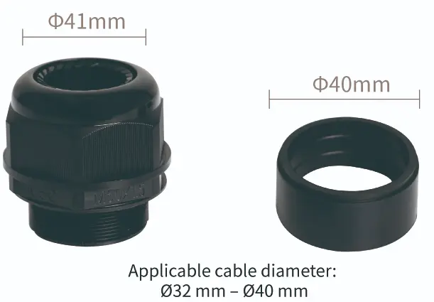 CG-M5015-40 |
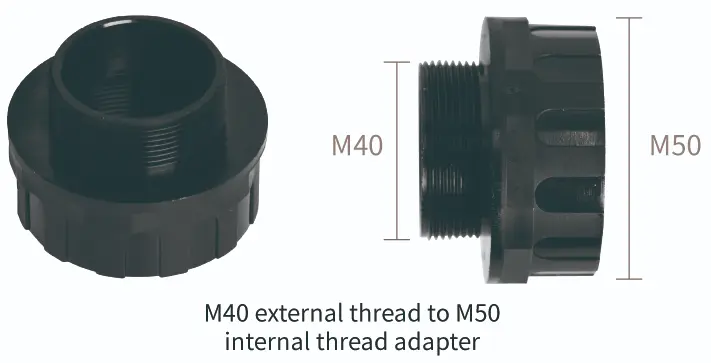 CG-M40-M50 |
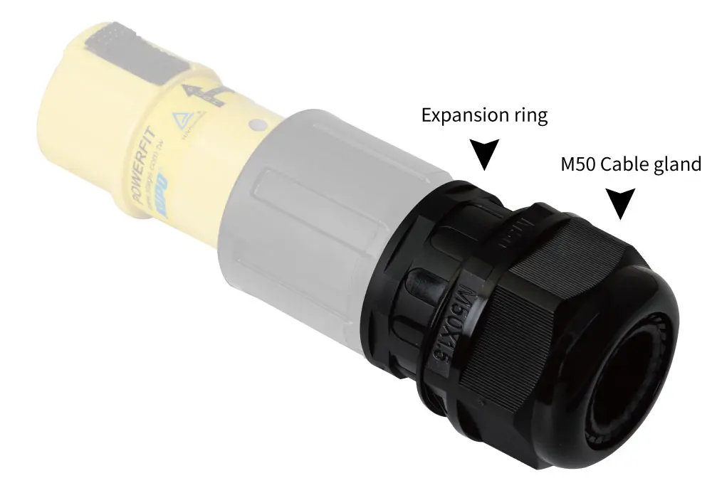
Weatherproof Protective Covers
| Part Number | Description | Notes |
|---|---|---|
| PF-DCT-M | Male weatherproof protective cover | Maintains environmental protection on unmated Source connectors. |
| PF-DCT-F | Female weatherproof protective cover | Maintains environmental protection on unmated Drain connectors. |
IP67 applies when mated. Use PF-DCT covers on any unmated connectors to maintain environmental protection across the full system. PDB-C1303 series cubic power distribution boxes (5 color variants) are also available for complete system builds. Contact KUPO for availability.
Certifications and Compliance
| Certification | Detail |
|---|---|
| TÜV Rheinland | Certified under ID 1111322264. Type Approved, Safety certified, Regular Production Surveillance. Independent third-party verification of product safety and quality. |
| CE | CE marked. Meets applicable European health, safety, and environmental requirements. |
| IP67 | Complete dust protection (6) and temporary water immersion up to 1 meter for 30 minutes (7). Applies when mated. Use PF-DCT covers on unmated connectors. |
| Flame Class | UL94-V0, the top rating in the UL94 vertical burn (V) series. Self-extinguishes within 10 seconds with no flaming drips. |
| RoHS | Compliant with RoHS (Restriction of Hazardous Substances) Directive. |
| REACH | Compliant with REACH (Registration, Evaluation, Authorisation and Restriction of Chemicals). |
PowerFit carries TÜV Rheinland and CE certifications (European certification path). For applications that require a UL listing (North America), see K-LOK: K-LOK 150A is cULus Listed (United States and Canada) and K-LOK 400A is UL Listed (United States), both under UL File E332947. For compliance documentation: contact KUPO Engineering.
Specs, Drawings, and CAD
Download the documents you need to complete a submittal package, mechanical design check, or procurement specification.
| Document | Format | Download |
|---|---|---|
| Product Family Datasheet | Download | |
| Full Catalog Extract | Download | |
| Installation and Assembly Guide | Download | |
| 2D Drawings (DXF / DWG) | ZIP | Download |
| 3D CAD Models (STEP / IGES) | ZIP | Download |
| Panel Cutout Template (42 × 42mm) | DXF | Download |
| Compliance Pack (TÜV, CB, CE, UKCA, RoHS) | ZIP | Download |
Need a document not listed here? Contact us and we will prepare it for your submittal package.
Installation and Assembly
Always de-energize circuits before mating or unmating connectors.
Line Connector Assembly (6 Steps)
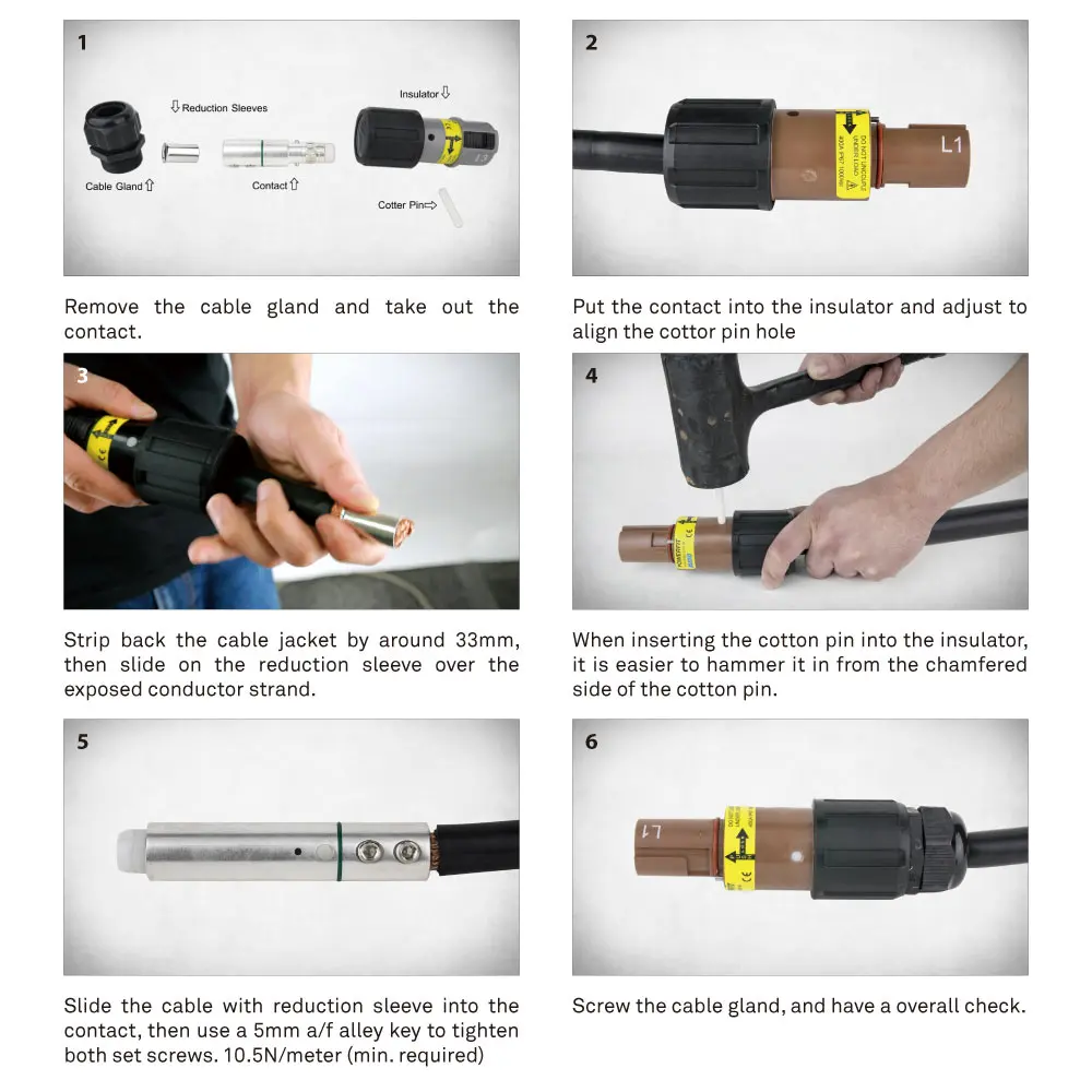
1. Loosen cable gland nut and remove gland body.
2. Thread cable through gland nut, then body.
3. Strip cable to spec (refer to datasheet).
4. Insert conductor into contact barrel, tighten set screw to 10.5 N·m minimum.
5. Seat contact assembly into housing until it clicks.
6. Reassemble cable gland and tighten for IP67 seal.
Panel Connector Installation (4 Steps)
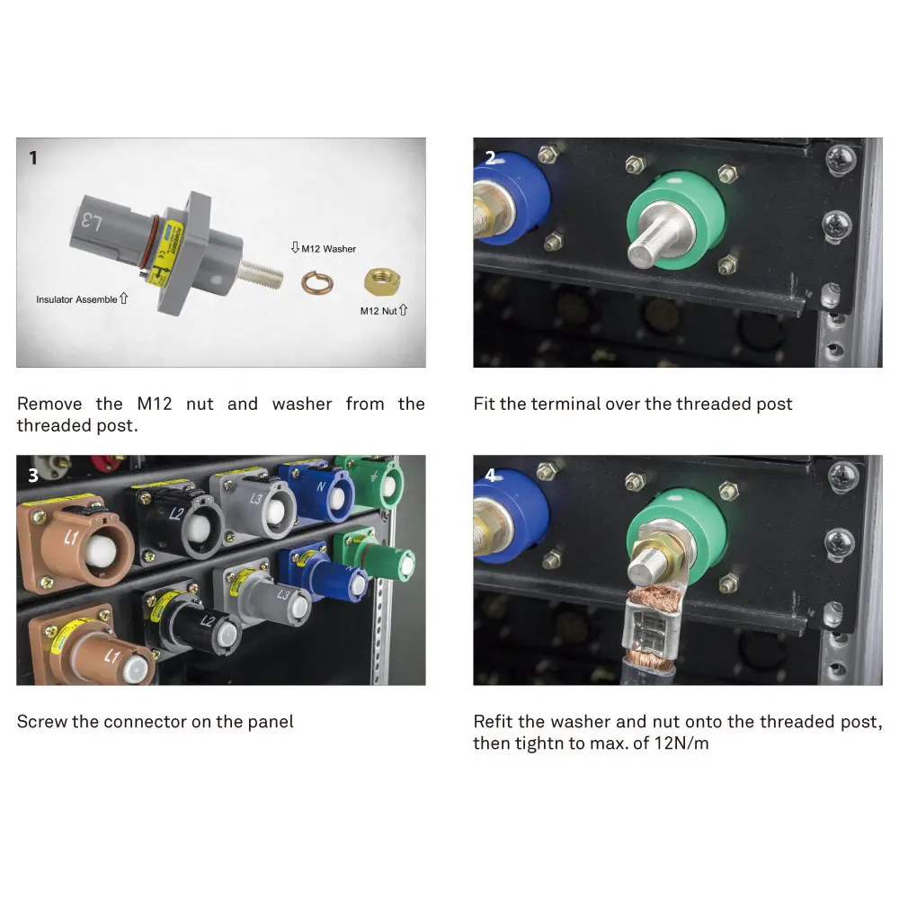
1. Cut a 47.5mm diameter panel opening and drill four 5.5mm fixing holes on a 42 x 42mm square.
2. Insert connector from rear, align flange with 4 fixing holes.
3. Connect conductor to M12 threaded post, tighten brass nut to 12 to 14 N·m max.
4. Secure flange with 4 screws. Remove plastic end cap before first mating.
Frequently Asked Questions
Can I disconnect a PowerFit connector while the circuit is live?
No. PowerFit single-pole connectors are not rated for load-break disconnection. Pulling a PowerFit connector while current is flowing creates an electrical arc that damages contacts, degrades the housing, and risks burns, shock, or fire. At 400A the arc energy can cause immediate injury. Always de-energize at the breaker, verify dead with a voltage tester, then disconnect.
What does IP67 mean, and does it apply when the connector is unmated?
IP67 means complete protection against dust ingress (rated "6") and temporary water immersion up to 1 meter for 30 minutes (rated "7"). This rating applies only when mated. The silicone O-ring on Drain connectors creates the waterproof seal when a Source and Drain pair are connected. For unmated connectors, use PF-DCT-M (male) or PF-DCT-F (female) weatherproof protective covers to maintain environmental protection during storage or when one side of a circuit is not in use.
What is the difference between Source and Drain?
Source connectors have the male contact (pin) and the key-release pin for controlled disconnection. Drain connectors have the female contact (socket) and the silicone O-ring that provides the IP67 seal. Electric direction flows: Panel Source → Line Drain ↔ Line Source → Panel Drain. Source always mates with Drain. The key-release pin on Source connectors can be operated tool-free or with a small slotted screwdriver. A diagram is available at the top of this page.
Why does the same color appear in multiple SKUs (for example, 1BK, 2BK, and NBK are all black)?
PowerFit uses phase-encoded SKU codes where the prefix indicates the electrical phase assignment, not just the physical color. Black can be L1 (1BK, common North American practice), L2 (2BK, under European IEC 60445), or Neutral (NBK, under Australian/old UK conventions). This system exists because the same physical color carries different phase meanings in different regional wiring standards. Ordering by phase-encoded SKU instead of color alone prevents dangerous cross-convention wiring errors. The phase tables on this page show which code matches your regional standard.
Does PowerFit carry a UL listing?
PowerFit carries TÜV Rheinland certification to IEC 61984 (ID 1111322264 for 400A and 500A; ID 1111304988 for 750A and 800A), CB and UKCA certificates, CE marking, and RoHS/REACH compliance. It follows the European certification path and does not carry a UL or cULus listing. For North American bid specifications that require a UL listing, KUPO offers K-LOK: K-LOK 400A is UL Listed to UL 1691 (United States) and K-LOK 150A is cULus Listed (United States and Canada), both under UL File E332947.
Need help choosing PowerFit 400A?
KUPO can help confirm source/drain configurations, phase-coded SKUs, compatibility, fleet pricing, and documentation.